Electromagnetic Induction
Overview
Electromagnetic induction is the production of an induced emf, and an induced current if the circuit is complete, when the magnetic flux linkage changes through a conductor or coil.
This topic is a major link between magnetism and electricity, and underpins electric power generation, transformers, microphones, pickups, braking systems, and many sensing devices.
A key exam idea:
Induction does not occur simply because a magnetic field is present. Induction requires changing magnetic flux linkage.
Core Ideas
Electromagnetic-induction questions revolve around a few linked ideas:
- magnetic flux measures how much field passes through a surface
- magnetic flux linkage includes the number of turns in a coil
- induced emf depends on the rate of change of flux linkage
- Lenz’s law determines direction by opposing the change
- induction can be produced by changing field strength, area, orientation, or relative motion
- eddy currents are a bulk-conductor consequence of changing flux
Exam Relevance
Students are expected to:
- use the correct angle in
- distinguish flux from flux linkage
- apply Faraday’s law in sign and magnitude form
- use Lenz’s law systematically for current direction
- interpret flux-time and emf-time graphs
- recognise when induction does or does not occur
Prior Links Between Electricity and Magnetism
Earlier topics established that:
- electric currents produce magnetic fields
- magnetic fields exert forces on moving charges and currents
See:
Electromagnetic induction completes the connection:
- changing magnetic conditions can produce emf and current
Key Representations
Magnetic Flux
Definition
Magnetic flux measures how much magnetic field passes through a surface.
For a uniform field:
where:
- = magnetic flux density
- = area of surface
- = angle between the magnetic field and the area normal
Angle Convention
This is one of the most common mistakes.
- is measured between the field direction and a line perpendicular to the surface
- if the angle to the plane is given, convert first
Maximum and Zero Flux
- maximum flux when field is perpendicular to the surface:
- zero flux when field is parallel to the surface:
Unit
Visual Reference
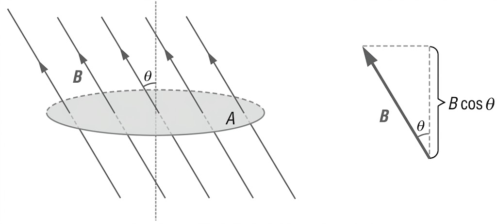
Figure 1: Magnetic flux through a surface depends on the perpendicular component of the magnetic field. The angle is taken relative to the surface normal, not the plane itself.
Magnetic Flux Linkage
For a coil with turns, the magnetic flux linkage is:
where:
- = number of turns in the coil
- = magnetic flux through one turn
Magnetic flux linkage represents the total magnetic flux linked with all turns of the coil.
Factors Affecting Flux Linkage
For a uniform magnetic field:
where:
- = magnetic flux density
- = area of the coil
- = angle between the magnetic field and the area normal
Hence the magnetic flux linkage changes if any of the following changes:
- number of turns
- magnetic flux density
- coil area
- orientation angle
Faraday’s Law
The induced emf equals the negative rate of change of magnetic flux linkage:
Average form:
Meaning of the Negative Sign
The negative sign represents Lenz’s law:
The induced emf acts in a direction that opposes the change in magnetic flux linkage producing it.
The negative sign determines the polarity of the induced emf such that, if the circuit is closed, the induced current produces magnetic effects opposing the change in magnetic flux linkage.
Thus, the negative sign is not merely a mathematical symbol to memorise; it expresses the physical principle described by Lenz’s law.
Hence:
- if the magnetic flux linkage through a coil increases, the induced current produces a magnetic field opposing the increase
- if the magnetic flux linkage decreases, the induced current produces a magnetic field opposing the decrease
The negative sign is therefore not merely a mathematical sign convention; it expresses the physical principle of conservation of energy.
Meaning
The magnitude of the induced emf increases when the magnetic flux linkage changes more rapidly.
Since:
a larger induced emf can be produced by:
- using more turns
- using a stronger magnetic field
- using a larger coil area
- rotating or moving the coil more rapidly
- changing the orientation more rapidly
Lenz’s Law
Lenz’s law states that the induced effects oppose the change in magnetic flux linkage producing them.
This is the physical meaning of the negative sign in Faraday’s law:
Why It Must Oppose Change
If the induced effects assisted the change in magnetic flux linkage instead of opposing it, the induced magnetic field would reinforce the original change in flux linkage.
For example, in a closed circuit, the induced current would produce a magnetic field that further increases the change in magnetic flux linkage, leading to a positive feedback effect.
Energy would then be continuously generated without external input, violating the principle of conservation of energy.
Direction of Induced Current in a Closed Circuit
General method:
- Decide whether magnetic flux linkage is increasing or decreasing.
- The induced field must oppose that change.
- Determine the induced field direction.
- Based on the induced field direction, use the right-hand grip rule to determine the corresponding current direction.
Ways to Produce Induction
Any method that changes flux linkage can induce emf.
1. Move Magnet or Coil
- magnet towards coil
- magnet away from coil
- coil entering or leaving field
2. Rotate Coil
Changes angle continuously.
3. Change Coil Area
Flexible loop expanding or shrinking.
4. Change Magnetic Field Strength
Increase or decrease electromagnet current.
5. Nearby Changing Current
Changing current in one coil changes the field through another coil.
Experimental Observations
Faster Motion Gives Larger emf
Move a magnet faster towards a coil:
- larger rate of change of flux
- larger galvanometer deflection
Reverse Motion Reverses Current
Moving a magnet away instead of towards the coil reverses induced current direction.
Switching Nearby Coil On or Off
When current in a nearby coil changes:
- magnetic field changes
- induced emf appears in the second coil
A steady current gives no induction after the field becomes constant.
Motional emf Overview
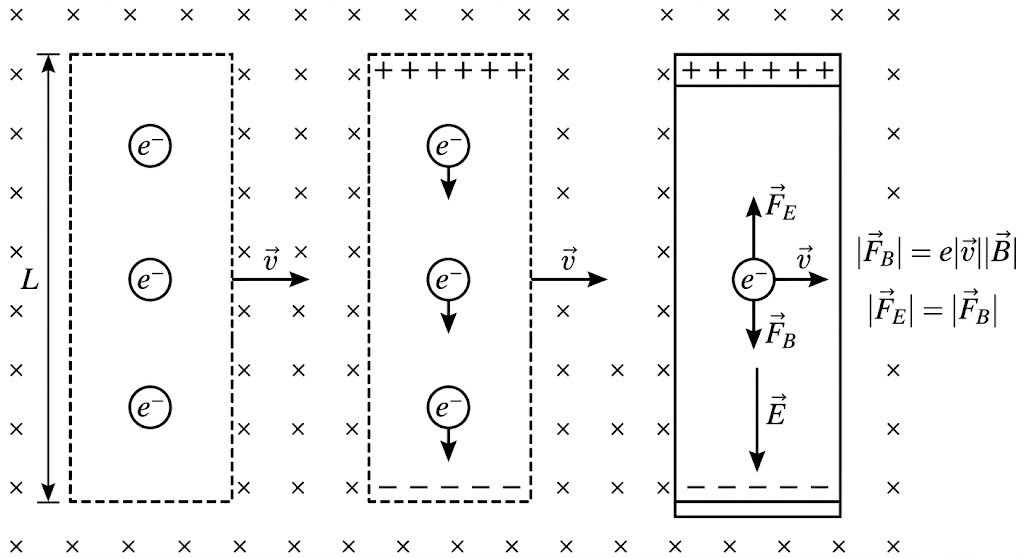 *Figure 2. Motional emf in a conductor moving through a uniform magnetic field into the page. As the conductor moves with velocity $\vec{v}$, electrons experience a magnetic force $\vec{F}_B$ downward and accumulate at the lower end, leaving positive charge at the upper end. This charge separation produces an internal electric field $\vec{E}$ downward, giving an electric force $\vec{F}_E$ upward on the electrons. At equilibrium, $|\vec{F}_E|=|\vec{F}_B|$, so a steady potential difference is established across the conductor.
If a straight conductor of length moves through a magnetic field, an emf is induced when the conductor cuts magnetic field lines. The induced emf depends on the component of the conductor’s velocity perpendicular to the magnetic field.
In the standard case where the conductor, its velocity, and the magnetic field are mutually perpendicular,
This motional emf arises because the magnetic force on the mobile charges in the conductor causes charge separation. The separated charges produce an electric field inside the conductor, giving rise to an electric force that opposes the magnetic force. At equilibrium, the electric force balances the magnetic force, and a steady potential difference is established across the ends of the conductor.
If the conductor has a smaller velocity component perpendicular to the magnetic field, the induced emf is reduced. If the conductor does not cut magnetic field lines, the induced emf is zero.
See Motional emf.
Eddy Currents
When bulk conductors experience changing flux, circular currents are induced inside the material.
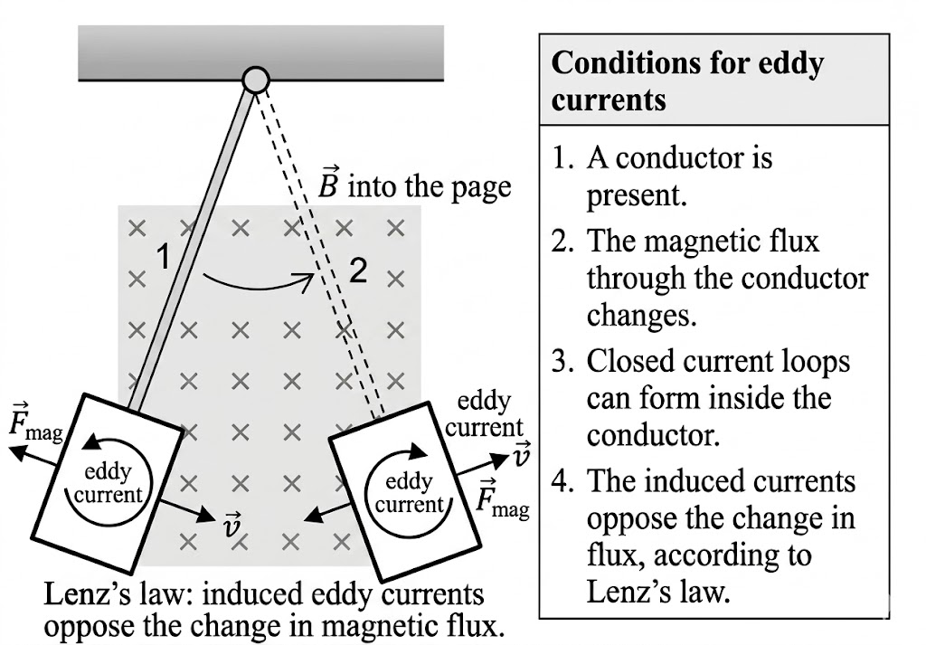
*Figure 3. Eddy currents are induced in a conducting plate as it swings through a magnetic field directed into the page. When the plate enters or leaves the field region, the magnetic flux through the conductor changes, producing circulating currents inside the plate. By Lenz’s law, these eddy currents produce magnetic effects that oppose the change in flux, resulting in a magnetic force opposite to the motion . This opposition causes magnetic damping and reduces the motion of the plate.
Effects
Heating Loss
Energy is dissipated as thermal energy.
Magnetic Braking
Opposing forces slow motion.
Damping
Used in moving-coil instruments.
Reduction
Use laminated cores or slotted metal sheets to reduce current loops.
Later Applications
Electromagnetic induction underlies several later applications, but those belong to their own topics.
- a rotating coil in a magnetic field gives alternating emf in an AC generator
- changing flux in a shared iron core induces emf in a transformer secondary coil
See:
Graph Skills
Flux-Time Graph
From Faraday’s law:
So:
- the negative gradient of a flux-linkage-time graph gives emf
- a steeper slope means larger emf
- zero slope means zero emf
Sinusoidal Relations
For a rotating coil in a uniform magnetic field:
- magnetic flux linkage varies sinusoidally
- induced emf also varies sinusoidally
- the induced emf is phase-shifted relative to the flux linkage
That relationship is important here because it links graph shape to Faraday’s law. The full generator treatment belongs in the alternating-current-generator topic.
Worked Examples
Example 1: Coil Rotated by
A coil initially has maximum flux linkage . It is rotated so the final flux linkage is zero in time .
Example 2: Magnet Held Still Near Coil
A magnet is stationary near a coil.
Change in flux linkage:
Therefore:
Example 3: Field Doubled in the Same Time Interval
Doubling the change in doubles the change in flux linkage, so the induced emf doubles.
Formula Sheet
Magnetic Flux
Flux Linkage
Faraday’s Law
Average Form
Motional emf
Common Pitfalls
- using angle to plane instead of angle to normal
- thinking presence of field causes induction
- forgetting flux linkage includes
- thinking maximum flux means maximum emf
- ignoring the sign meaning in Faraday’s law
See Electromagnetic Induction Common Exam Traps.