Magnetic Fields
Overview
Magnetic fields describe the region around magnets and moving charges where magnetic effects are observed. In Topic 16, the focus is on reading, sketching, and interpreting field patterns correctly rather than on force-law derivations.
This topic is closely linked to:
- Current Electricity Fundamentals
- Magnetic Fields from Currents
- Solenoids and Electromagnets
- Magnetic Fields Common Exam Traps
- Magnetic Force
Core Ideas
- magnetic fields are represented by field lines and magnetic flux density
- field-line direction and spacing show field direction and strength
- conventional current produces magnetic fields around wires and coils
- the right-hand grip rule is the standard direction tool for current-produced fields
- solenoids produce an approximately uniform internal field and behave like bar magnets
- a ferrous core strengthens the field in an electromagnet
- vector form should be used by default; signed-scalar form is a special one-dimensional simplification
Exam Relevance
Students are expected to:
- interpret field diagrams and direction conventions correctly
- distinguish straight-wire, coil, and solenoid field patterns
- use the right-hand grip rule with conventional current
- use standard proportional reasoning or simple formulas for current-produced fields
- explain why solenoids and electromagnets behave the way they do
1. Magnetic Field Representation
A magnetic field is a region where magnetic effects can be detected, for example by the force on a magnetic pole, a current-carrying conductor, or a moving charge.
The field is represented by magnetic flux density:
Its magnitude is , and the SI unit is the tesla, T.
Field Lines
Magnetic field lines are imaginary lines used to show field direction.
- the tangent to a field line gives the field direction at a point
- the direction is the direction of force on a free north pole at that point
- field lines do not intersect
- outside a magnet, field lines conventionally go from north pole to south pole
- inside the magnet, the loop continues back from south to north
- closer spacing means a stronger field
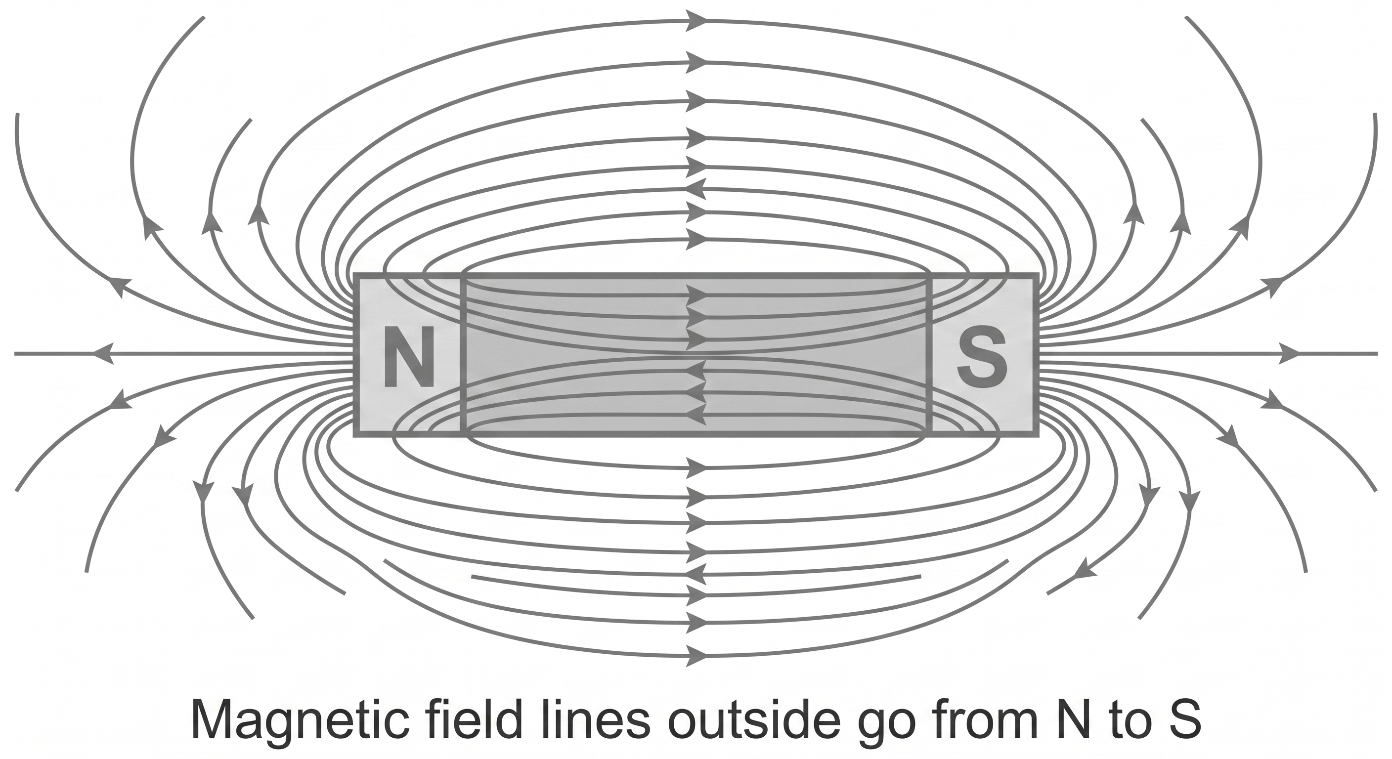 *Figure 1. Field lines around a bar magnet leave the north pole and enter the south pole outside the magnet.*
Dot-and-Cross Notation
In a 2-D diagram:
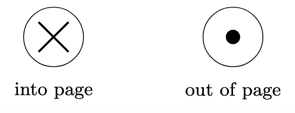
- crosses mean the field is into the page
- dots mean the field is out of the page
- this is a plan-view convention for a field perpendicular to the page
- it is especially useful when the field direction cannot be shown conveniently by ordinary arrows
 Dot-and-cross notation shows a field perpendicular to the page.
Uniform and Non-Uniform Fields
A uniform field has parallel, evenly spaced field lines and constant direction.
A non-uniform field has changing spacing and often changing direction.
Examples:
- approximately uniform: central region of a long solenoid
- non-uniform: field near a bar magnet, straight wire, or short coil
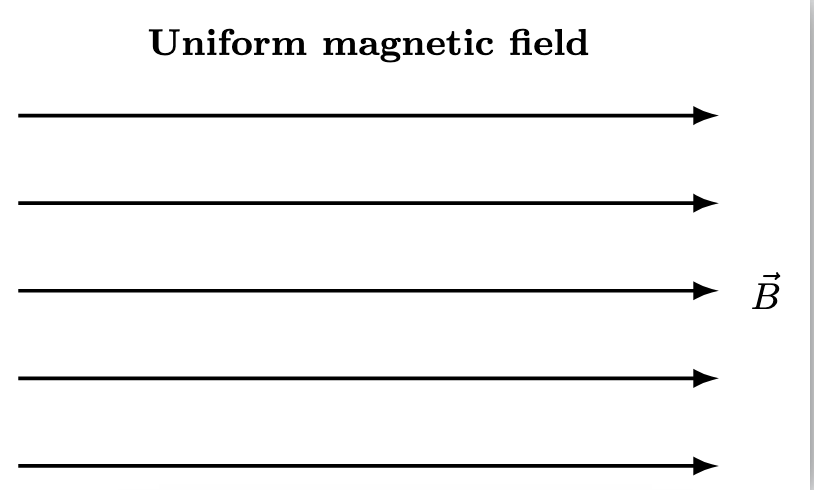 A uniform magnetic field is represented by parallel, equally spaced lines.
Summary
Field lines, dot-and-cross notation, and spacing all encode direction and relative field strength rather than literal particle paths.
 *Figure 2. Basic rules for representing magnetic fields. The tangent to a field line gives the magnetic field direction at a point, $\times$ denotes a field directed into the page, $\bullet$ denotes a field directed out of the page, and closer field-line spacing indicates a stronger magnetic field.*
2. Magnetic Fields Due To Currents
Electric current produces a magnetic field because current is moving charge.
The field pattern depends on the geometry of the conductor. In this topic, that pattern is often called the magnetic flux pattern.
The important exam skill is not only to recognise the pattern, but also to connect:
- geometry of conductor
- direction of conventional current
- direction of magnetic field
- how field strength changes with position
Right-Hand Grip Rule
- thumb points in the direction of conventional current
- curled fingers show the direction of the magnetic field
This rule applies to wires, coils, and solenoids.
By default, the magnetic field should be expressed in vector form, with direction supplied either by the field pattern or by the right-hand grip rule. A signed-scalar form is acceptable only after a one-dimensional direction convention has been stated explicitly.
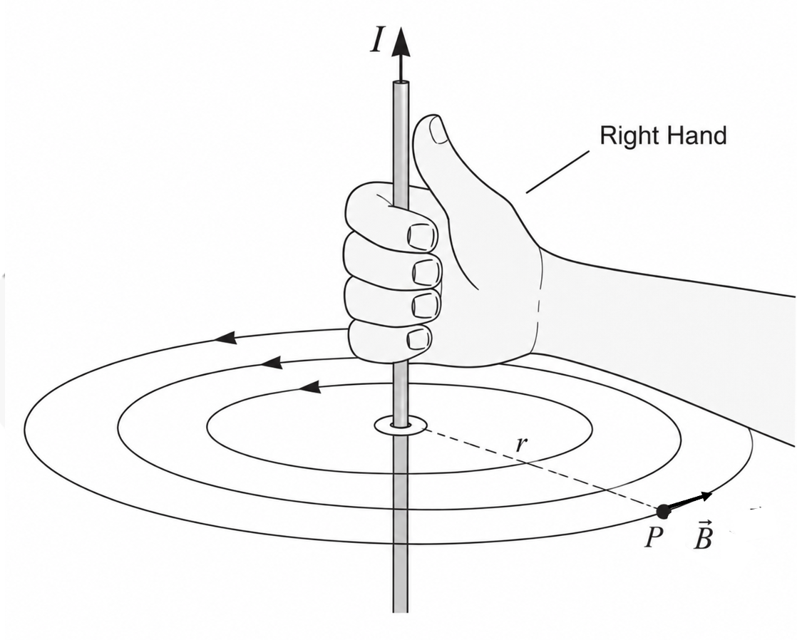 *Figure 3. Right-hand grip rule for a straight current-carrying wire. The thumb points in the direction of conventional current \(I\), while the curled fingers indicate the circular magnetic field direction. At point \(P\), the magnetic field vector \(\vec{B}\) is tangent to the circular field line at radial distance \(r\).*
### Long Straight Wire
*Figure 3. Right-hand grip rule for a straight current-carrying wire. The thumb points in the direction of conventional current \(I\), while the curled fingers indicate the circular magnetic field direction. At point \(P\), the magnetic field vector \(\vec{B}\) is tangent to the circular field line at radial distance \(r\).*
### Long Straight Wire
Around a long straight wire, the field lines are concentric circles.
The standard expression is:
where is the perpendicular distance from the wire and is the tangential unit vector around the wire.
If only the magnitude is needed, then:
Trends:
- increasing current increases
- increasing distance from the wire decreases
- reversing the current reverses the magnetic field direction
- increasing spacing between successive field circles indicates the field is weakening with distance
Flat Circular Coil
A flat circular coil concentrates its field through the centre.
At the centre of a coil with turns and radius :
where is a unit vector perpendicular to the plane of the coil, with direction determined by the right-hand grip rule.
If only the magnitude is needed at the centre, then:
The field through the centre is approximately perpendicular to the plane of the coil.
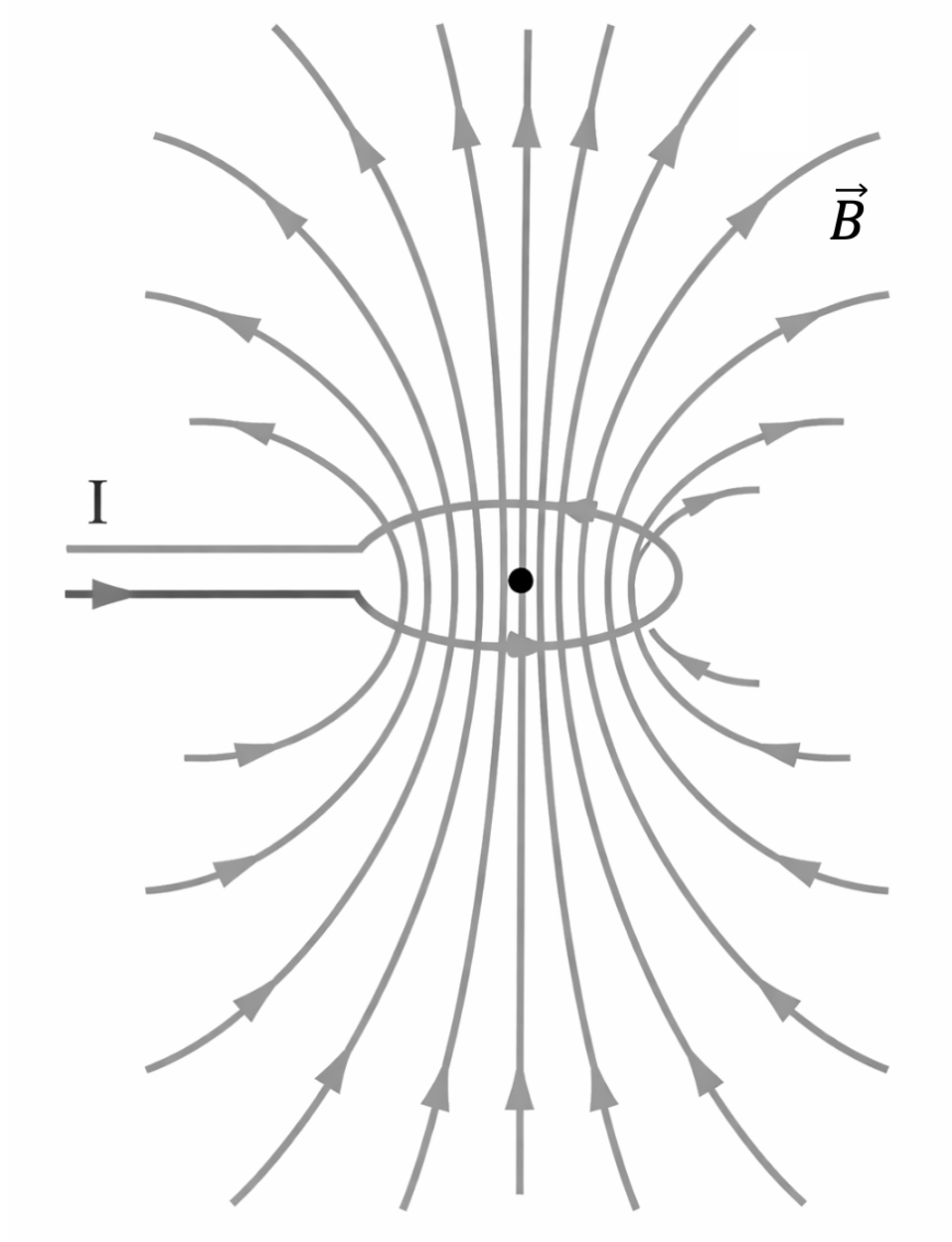 *Figure 4. Magnetic field around a circular current-carrying coil. The magnetic field lines are concentrated through the centre of the coil, where the field is strongest. The black dot marks the centre of the loop.*
### Long Solenoid
*Figure 4. Magnetic field around a circular current-carrying coil. The magnetic field lines are concentrated through the centre of the coil, where the field is strongest. The black dot marks the centre of the loop.*
### Long Solenoid
A solenoid is a long coil of closely spaced loops.
Inside a long solenoid:
- field lines are straight
- field lines are parallel to the axis
- the field is approximately uniform
Outside the solenoid:
- the field pattern resembles that of a bar magnet
- the field is much weaker than inside, not zero
For an ideal long solenoid:
where is the number of turns per unit length and is the unit vector along the solenoid axis.
If only the magnitude is needed in the central region, then:
The field at either end is about half the central value in the ideal model:
For a nearly ideal long solenoid:
- the field in the central region is approximately uniform
- the field outside is very weak compared with the field inside
- the external field pattern resembles that of a bar magnet
- the north and south ends can be identified from the field-line direction
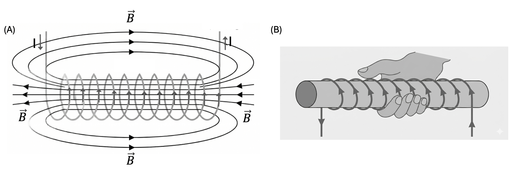 *Figure 5. (A) Magnetic field pattern of a current-carrying solenoid. The magnetic field inside the solenoid is approximately uniform and stronger than the external returning field. (B) Right-hand grip rule for a solenoid: when the fingers curl in the direction of conventional current around the coil, the thumb points in the direction of the internal magnetic field and toward the North pole.*
Magnetic field pattern of a solenoid, with a strong nearly uniform field inside and weaker returning field lines outside.
3. Solenoids And Electromagnets
A solenoid acts like a magnet only when current flows.
Adding a ferrous core such as soft iron increases the field strength because the material has higher permeability than air and becomes magnetised by the solenoid.
This is the basis of an electromagnet.
Good exam phrasing:
- the field inside is stronger
- the outside field is much weaker
- the poles follow the right-hand grip rule
- the current can be switched on and off
- the ferrous core strengthens the field but does not change the basic flux pattern
Why the ferrous core matters
The anchor notes emphasise two equivalent ways to explain this.
- A ferrous core has much higher permeability than air, so the magnetic flux density becomes larger for the same current and turn density.
- A ferromagnetic core becomes magnetised in the solenoid field, so it contributes to the overall magnetic field produced.
Both explanations support the same exam conclusion: a current-carrying solenoid with a ferrous core is a stronger electromagnet than the same solenoid with an air core.
4. Quick Comparisons
- straight wire: circular field lines around the wire
- circular coil: strong field through the centre
- long solenoid: nearly uniform field inside, bar-magnet-like outside
The simplest comparison logic is:
- wire geometry spreads the field around the conductor
- circular-coil geometry concentrates the field through the centre
- long-solenoid geometry makes the internal field much more uniform
5. Topic Boundary
Keep this topic focused on field representation and current-produced fields.
Do not expand this hub into:
- force on a current-carrying conductor
- force on moving charges
- velocity selection
- electromagnetic induction
Those belong to later topics or separate concept notes.