Equilibrium, Moments, and Couples
Overview
Equilibrium, Moments, and Couples develops the statics part of Forces. It explains how objects remain balanced translationally and rotationally.
This page focuses on:
- moment of a force
- turning effects and rotational sense
- couple
- torque of a couple
- principle of moments
- conditions for equilibrium
- centre of gravity
- stability and toppling
- choosing pivots
- worked examples
- exam pitfalls
These ideas are heavily tested in beam, ladder, hinge, support, and balance problems.
Why It Matters
Static equilibrium problems require both force balance and moment balance. A body can have zero resultant force but still rotate if the resultant moment is not zero.
Definition
A body is in static equilibrium when it has no translational acceleration and no angular acceleration.
Key Representations
Here, we have used to denote moment.
What is Equilibrium?
A body is in equilibrium when it has:
- no linear acceleration
- no angular acceleration
For a rigid body, two conditions must both be satisfied.
Translational Equilibrium
Rotational Equilibrium
where the sum of clockwise moments equals the sum of anticlockwise moments about the same pivot.
Force is a Vector
Force has magnitude and direction.
Examples:
- weight
- normal force
- tension
In one dimension, signed scalar components may be used after choosing a positive direction.
Moment of a Force
A moment is the turning effect of a force about a point or pivot. In vector form, it can be expressed as .
Magnitude:
where:
- = perpendicular distance from pivot to line of action of force
SI unit:
Proof (not required) — We start from the definition of torque:
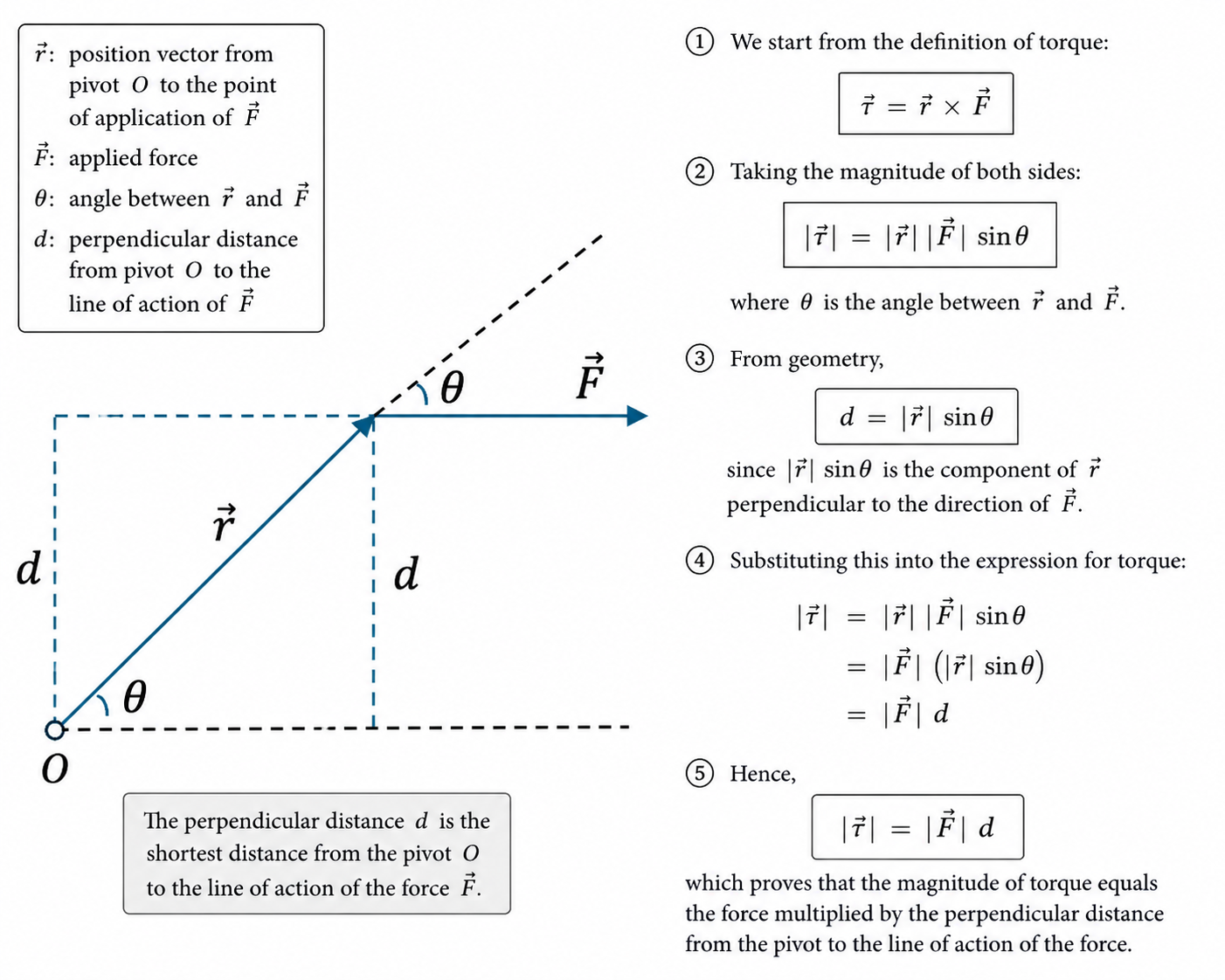
Figure: The perpendicular distance formula for moment follows directly from the cross-product definition .
Taking the magnitude of both sides:
where is the angle between and .
Now consider the perpendicular distance from the pivot to the line of action — The straight line that extends infinitely in both directions along the direction of the force, passing through its point of application — of the force. From geometry,
since is the component of perpendicular to the direction of .
Substituting this into the expression for torque:
Hence,
which proves that the magnitude of torque equals the force multiplied by the perpendicular distance from the pivot to the line of action of the force.
Direction / Sense of a Moment
Moments may be described as:
- clockwise
- anticlockwise
If using sign convention, define clearly, e.g.
- anticlockwise positive
- clockwise negative
Then rotational equilibrium may be written:
Perpendicular Distance Matters
Use the shortest perpendicular distance from pivot to the line of action of the force.
Not the slanted distance to point of application.
This is one of the most common mistakes.
Example of Moment
A force acts perpendicular to a spanner from pivot.
Couple
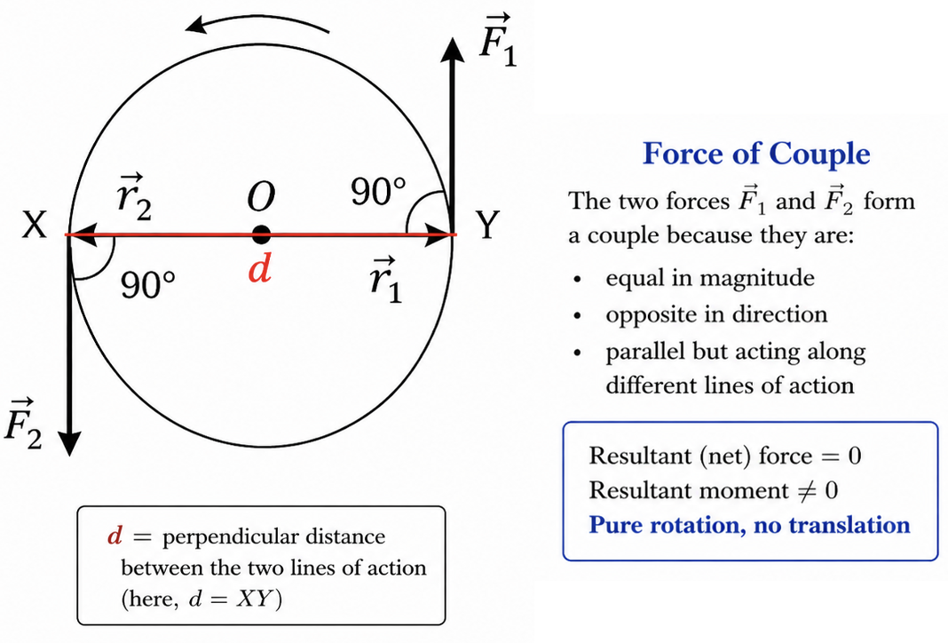
Figure: A couple is formed by two equal and opposite parallel forces whose separated lines of action give a non-zero resultant moment.
A couple consists of:
- two equal forces
- opposite in direction
- parallel
- separated by distance
- lines of action do not coincide
A couple causes rotation only. No resultant force.
Torque of a Couple
Magnitude:
where:
- = the magnitude of one of the forces
- = perpendicular distance between lines of action
Key Difference from Single Force
A single force may cause translation and rotation.
A pure couple causes rotation only.
Principle of Moments
For a body in equilibrium:
Sum of clockwise moments = Sum of anticlockwise moments
Equivalent form:
about any chosen pivot.
This is often the fastest way to solve support-force problems.
Choosing a Pivot
Choose a pivot through an unknown force when possible.
Why?
That force then has zero moment arm and drops out of the moment equation.
This simplifies calculations greatly.
Conditions for Equilibrium
Full Rigid-Body Equilibrium
Use both:
and
In Components
For 2D systems, using signed scalar in each direction:
Here, , and are signed scalars.
Centre of Gravity
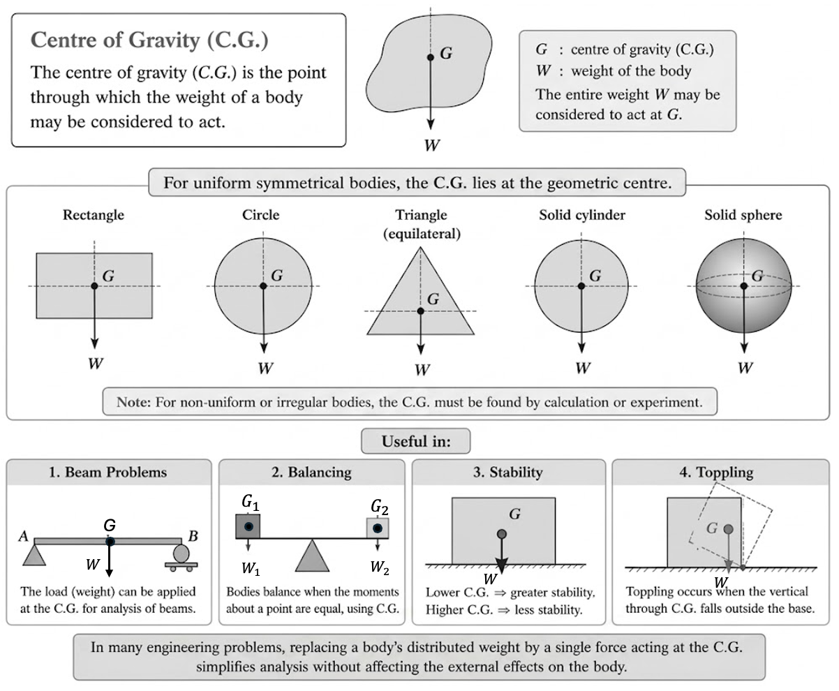
Figure: The centre of gravity is the point through which the resultant weight of the body acts.
The centre of gravity (C.G.) is the point through which the weight of a body may be considered to act.
For uniform symmetrical bodies, it lies at the geometric centre.
Useful in:
- beam problems
- balancing
- stability
- toppling
Stability
A body is stable if small displacement does not cause it to topple easily.
Greater Stability When:
- lower centre of gravity
- wider base area
Toppling Condition
The body topples when the line of action of weight passes outside the base.
For more detail on centre of gravity, toppling, and stability trends, see Centre of Gravity and Stability.
Uniform Beam Ideas
For a uniform beam:
- weight acts at midpoint
- if mass of beam is significant, include beam weight
- support reactions may act at ends / hinges
Three Coplanar Forces in Equilibrium
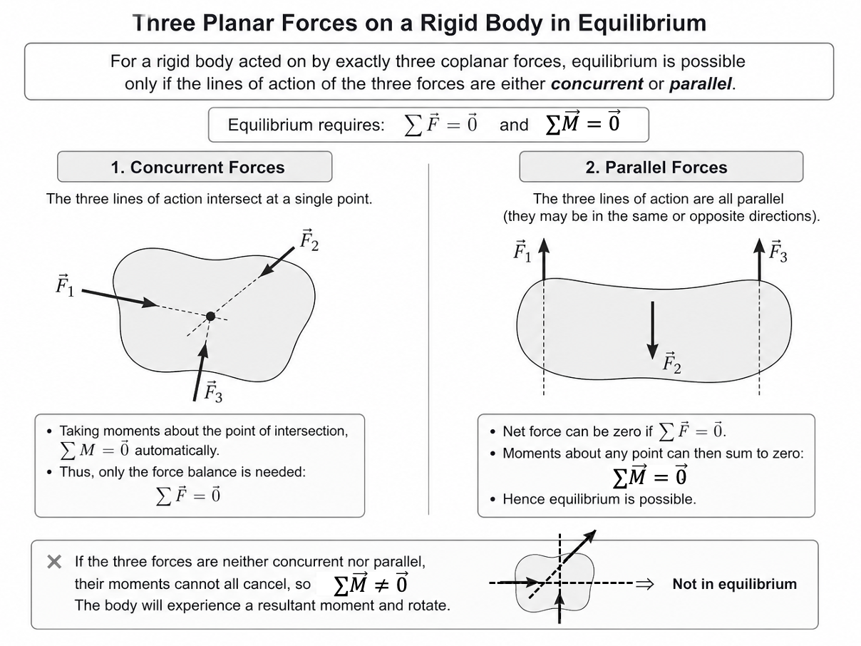
Figure: For equilibrium under exactly three coplanar forces, the lines of action must be concurrent or all parallel.
For a rigid body acted on by exactly three coplanar forces, equilibrium is only possible if the lines of action of the three forces are either concurrent (intersect at a single point) or all parallel. This result follows directly from simultaneously satisfying both equilibrium conditions:
If the forces are concurrent, all moments about the point of intersection are automatically zero, so only force balance is required. If the forces are parallel, both force balance and moment balance can be satisfied through appropriate magnitudes and positions. Importantly, this is a special result for exactly three forces and does not extend to four or more coplanar forces, where no such geometric constraint exists and equilibrium must be determined purely by applying the general conditions above.
Worked Examples
Example 1: Balanced Beam
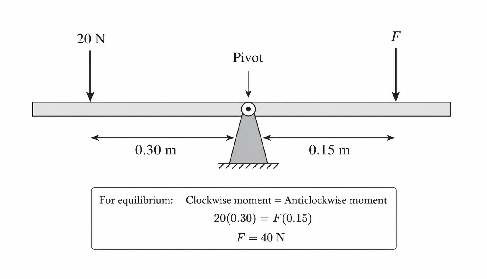
Figure: Taking moments about the pivot gives the balance condition for forces acting at different distances.
A beam is pivoted at centre. A force acts left of pivot. Find force needed right of pivot.
Clockwise moment = Anticlockwise moment:
Note: Clockwise moment = Anticlockwise moment is a result from . Denoting anticlockwise as positive, implies: , resulting in .
Example 2: Ladder / Rod Support
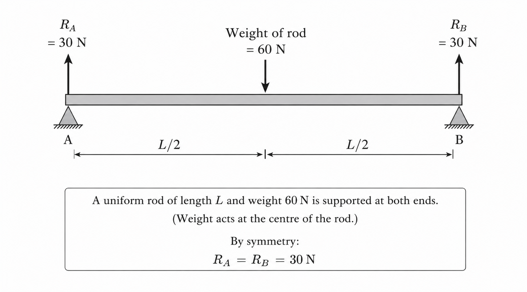
Figure: For a uniform beam in symmetric support, equal lever arms give equal support reactions.
A uniform rod weight is supported at both ends.
Symmetry gives equal reactions:
Example 3: Couple
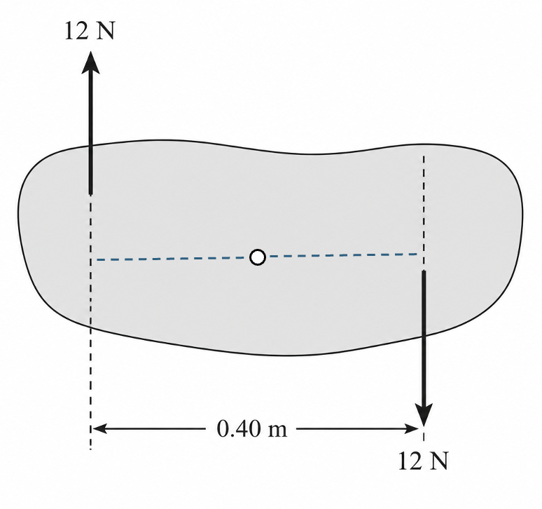
Figure: A couple consists of two equal and opposite parallel forces that produce a pure turning effect.
Two opposite parallel forces separated by . Both forces exert the same clockwise moment of . So the torque of the couple, which is the resultant moment, is:
Example 4: Sign Board Balance
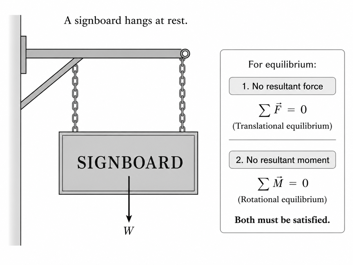
Figure: A hanging signboard must satisfy both force balance and moment balance to remain at rest.
A signboard hangs at rest.
Then:
and
Both must be satisfied.
Example 5: Flagpole Balance
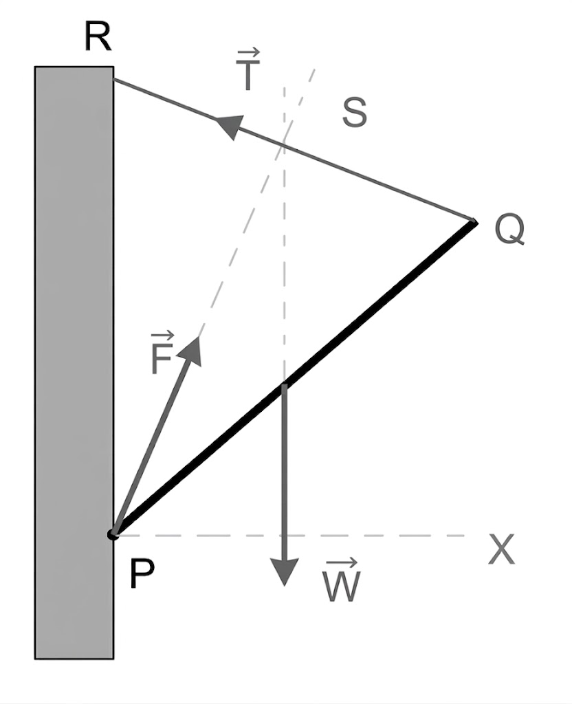
Figure: In a three-force equilibrium problem, the lines of action of the forces determine the hinge reaction direction.
A uniform flagpole is hinged to a vertical wall at point .
The free end is supported by a wire attached to a point on the wall.
The flagpole has weight acting at its midpoint, and the tension in the wire is .
Determine the direction of the force exerted by the wall on the flagpole at the hinge .
This is a problem about equilibrium under three coplanar forces. The lines of action of the three forces must meet at a point, so the direction of is determined.
Typical Procedure for Statics Problems
- Draw free-body diagram.
- Label all forces.
- Choose axes.
- Apply:
- Take moments about convenient pivot.
- Solve unknowns.
- Check units and reasonableness.
Common Exam Pitfalls
1. Using wrong distance in moment
Use perpendicular distance to line of action.
2. Forgetting beam weight
Uniform beam weight acts at midpoint.
3. Using only force balance
Rigid body equilibrium usually needs moment balance too.
4. Wrong turning direction signs
Choose convention and stay consistent.
5. Calling a single force a couple
A couple needs two equal opposite separated forces.
6. Forgetting reaction forces at supports
Hinges and supports often exert unknown reactions.
7. Assuming centre of gravity always at geometric centre
Only true for uniform symmetrical bodies.
Summary
Core Equations
Force Equilibrium
Component Forms
Moment magnitude of a Force
Rotational Equilibrium
Magnitude of the Torque of a Couple
Big Ideas
- forces balance translation
- moments balance rotation
- couples rotate without translation
- choose pivots strategically
- stability depends on base and C.G.